Last year, my partner and I moved into a new (to us) house. One of the first things I needed to get done was to get our home network setup as we both were (still are) working from home due to COVID-19. This post will explore some of that process, some of the decisions I made along the way, what I learned, and some details on the end setup.
Deciding on a Network Layout
The first step I took on was the overall layout of the network was going to look like. Some of the questions I had to think through:
- Where was the internet connection going to enter the house?
- The FiOS ONT terminated in the Garage. So if I wanted to use ethernet straight from the ONT, I would need to run ethernet from inside the house to the ONT.
- Did I want a wired backbone, or a mesh network backbone?
- How much do I want to design for the future vs keeping focused on the present?
- How many wired devices do I intend on supporting?
- For the home office, is WiFi acceptable? Or do I want to have the devices wired in there?
One of the first decisions I made here was that I wanted the network to be as wired as possible. I wanted the reliability, speed, and upgradability of having ethernet throughout the house and in most rooms. So that dictated a lot of the decisions that follow, as I need to be running ethernet cabling.
The next problem to solve is how to run the cables through the 2 story house with an attic and a basement. Do I run everything from the basement to the rest of the house? Do I have a networking station on each floor? Do I put most of it in the attic? After looking at the floor plan considerably, there wasn’t really many first and second floor walls that both lined up well with each other, and were in a good space to access from either above or below. In fact, I only found one wall that would be “easy” to access from all 4 floors (including basement and attic).
This settled me on a “tiered” network architecture. I would separate the upstairs and the downstairs into two distinct segments, and connect them with a “backbone” network layer. I then picked the location of the two network wiring closets. For the downstairs segment, I chose a wall that was adjacent to the garage, which would allow easy wiring to the garage and good access to the rest of the first floor. For the upstairs segment, I selected a tall closet in our future office. This had easy access to the attic, as well as good power and a central location.
So my overall layout was set. I’d have a network rack in the basement which housed my router, a switch for the downstairs network drops, and a switch in the office closet upstairs for the upstairs network drops.
The one final layout problem to solve is where to put the WiFi access points. This has more to do with the layout of the house than anything, so I won’t go into much detail here. The one thing I did was to get a 100 foot ethernet cable, and test different locations for each access point (using a mobile phone app). Once I settled on the locations, they were very similar to wiring ethernet jacks to the network closets, so won’t go too much more detail here.
Deciding on the Hardware
Now that I had my backbone physically located, I needed to decide how to connect the backbone. I could run ethernet between them, but I wanted to future proof it as much as possible. Given that it wasn’t a short run (about 150 feet, or 45 meters), I made the decision to run fiber for the backbone. I went through a few options, and settled on running two different fiber cables. One multi-mode OM4 and one single-mode OS2. Why not just go with 2 multi-mode or 2 single mode? I don’t know. I couldn’t decide, so I just decided why not one of each. I’d only really be using one at any one point in time (leaving the other as a backup). It should also be sufficiently future-proof (OS2 with different networking transceivers are capable of 400gbps+).
For the rest of the house, I wanted to be as future proof as I could reasonably be, while not going totally overboard (so not running fiber to every room). So I settled on CAT6a cabling in a F/UTP configuration (an outer foil shield, but each pair is unshielded). This is a bit harder to work with (a thicker and less flexible cable), but should be solid for 10gbps ethernet if I ever want to upgrade to it. I made this decision because, at the end of the day, it’s a ton of work to pull all that cable and I’d rather only do it once. I could have gone for CAT7, but the added expense didn’t seem worth it considering at the lengths I am running the bandwidth would likely be very similar (both 10gbps) with CAT7 only maybe theoretically supporting 100gbps on the shorter runs. So I got 2 1000-foot spools of CAT6a F/UTP, and a bunch of keystone jacks.
For the patch panels, I found that there were few that supported CAT6a, and those that did were bulky and cumbersome. Then I found one by Trendnet. This turned out to work really well, so I got 2 and went to the races.
In prior homes (and offices) I have had really good luck with UniFi networking gear, so I started with the assumption that I would use that for this house. I settled on the UniFi Dream Machine Pro for the “router”, a set of 10gbps switches for the backbone (UniFi Switch 16XG, and picked PoE (Power over Ethernet) 1gbps switches for the rest.
I did look at the Mikrotik hardware, and while the price was amazing, I really wanted the central management ability of UniFi.
Tools and Consumables
Before I talk through how I pulled cable, etc, I think it’s important to touch on what sorts of tools were needed for this. Here’s a rough list of the tools I used and would suggest you get as well:
- A razor blade utility knife - For cutting through drywall to make the holes for the network wall plates
- A 3/4 inch Flex Drill bit - For making holes inside of walls to run cables up or down to the next floor.
- A Flex Drill Extension - Very useful to go “up” through a wall or get longer reach with the flex drill.
- A Fiberglass Fish Rod Kit - Definitely get much longer than you need. Very useful for pulling cable and finding routes within walls.
- An Endoscope (borescope) camera - Hands down the best $60 I spent. If you’re working inside of walls, you need this to stay safe. This helped prevent me from drilling through water pipes at one point, so I highly recommend it to everyone.
- A stud finder
- A network cable tester - Don’t go too crazy here, but definitely test every cable you run.
As far as consumables, I won’t list everything here, but the things that I found to be worth while over the “common” things you’ll find:
- Single-Gang Drywall Brackets - So much better than the plastic versions. Used to “trim out” the hole for the individual network drops and secure the wall plate to the wall.
- Trendnet CAT6a Keystones - These are definitely not cheap, but I found them to be the most reliable to terminate and the easiest to work with.
- Nylon Pull Line - Use this to pull the cable through the wall.
Pulling The Cabling
Before we talk about the actual pulling, I think it’s important to start with a simple rule: never pull just one cable. Pulling cable is a pain in the neck, and if you think you need one cable, pull two. If you think you need two, pull four. And if you think you need four, pull six. It’s so much easier to pull while you’re setup than to come back in a few years because a cable failed or your needs changed.
One technique that I accidentally found is basically always go from the area of least access to the area of most access (or from hard to easy). For most of the first floor runs, that was often going from the first floor down into the basement (as the basement was more open). Similarly with most of the upstairs runs (going up from the upstairs into the attic). However, there were some runs that were odd (that required going from hard to easy to hard, or easy to hard to easy). In those cases, I would often pull a nylon pull line in the “normal” direction (from hard to easy), do the same with the other part of the run (with a new nylon line), then tie the two together. This allowed for the run to be continuous and still navigate some significant challenges.
For “normal” runs through walls, I always started with the stud finder. I found an approximate area on the wall I wanted the network jacks. Then I would find where the studs were on either side, and put masking tape (so not to damage paint). If I was going up (to the attic for example), I would also run the stud finder up to the ceiling to see if there is a fire-block (a piece of wood blocking off the wall). If so, I would usually switch to a different stud bay and try to find one without a block. If you can’t find another, then you’ll have to drill through.
There are a ton of YouTube videos on drilling and running wires through walls, so I won’t go too in-depth here. A few pieces of advice though:
Take your time. You’re drilling blind, and there are multiple things behind the drywall that don’t react well to drills (ducts, electrical wiring, water pipes, etc). Before you cut into the wall, do your best to check for air ducts and electrical wires. Once you cut into the wall, use the borescope to look inside the wall before every step you take. Sometimes you’ll find pre-existing holes you can re-use if you get the angle just right (the fish rod comes in real handy with that). When you do drill, go in bursts and inspect whenever you feel a breakthrough. One of the times I did, I found a set of copper water lines running right under the hole. Had I kept pushing, I’d have had a flooded house…
Leverage gravity whenever you can. Going from top down is often FAR easier than trying to go bottom up (though not always). One trick I found really handy here is to drill a tiny hole in the ceiling next to the wall where I want the cable to pass into the attic. Then, I’d push a piece of small wire (like 1/8” or 3mm in diameter) up. That way, when I find the wire in the attic, I am able to locate where to drill (after offsetting to the wall). Then I can drill my normal 3/4 inch hole in the top of the wall, and push the fish rod down into the wall and grab it from the hole.
Plan. Plan. And Plan some more. Find reference points on each floor that you can measure from so that you can understand where you are operating on each floor and visualize the step in 3D. For example, in the basement I would find air vents that go up into the wall, and then use the position of the vent to measure offsets.
Label your cables before you pull them. I pulled two cables at a time with 2 spools. I labeled one of the spools “A” and the other “B”. Before pulling, I’d label the end of each cable with the room name and cable number for that room (ex: Bedroom 1 and Beddroom 2). Then after pulling, when I cut the cable from the spool, I label the cut end. It’s easy to keep track of, because the “A” spool always has a odd cable number (“Bedroom 1”, “Bedroom 3”, etc), and the “B” spool always has an even cable number. Label when you punch the cables into the patch panel as well.
Test as you go. When you run a cable, punch it in and terminate it at both sides, then test it. If you test every one as you install it, you’ll never have an untested cable (and risk damaging equipment you plug in).
Sometimes you will need two people to complete a run. Some cable runs are just too tricky to do by yourself, so having someone feeding cable up who can pull/push as needed can make life a lot easier.
When using a spool of cable, always rotate the spool to feed cable off it as if you just pull cable off the end you’ll get a twist and result in kinks. Get a wooden rod or some other method to unspool the cable. Initially I 3D printed some rollers, but they weren’t the best. Eventually I just moved to using an old closet rod to unspool.
Always leave yourself slack on both ends when pulling cable. At the wall end, I normally would leave enough for a small loop inside the wall, to allow me to work a foot or two outside the wall when installing the keystones, and in case I made a mistake and had to cut and re-terminate.
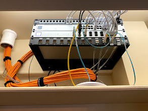
Neatness counts. Get yourself a lot of velcro strips, and bundle the cables together as you go. It’s much easier to build up a neat bundle as you go rather than after the fact. Here’s an example of how the upstairs network closet came out:
Finally, don’t get frustrated. If you encounter a major obstacle, take some time and reset. Think through the problem and find a solution. Don’t be afraid to change your plans. There’s no need to get too flustered. As an example, I ran into heavily insulated interior walls when I was wiring the upstairs. It was such a pain in the neck I almost stopped and called a company to come finish. After thinking through it for a bit, I decided to try to come down from the attic and while it wasn’t trivial it was way easier.
One REALLY important note: every time you drill a new hole in the floor or ceiling stud header, you potentially compromise the fire rating of the wall. Know your local building code and how to keep safe. For mine, it involved sealing those holes with fire block (a sort of clay that you mold to take the space).
Setting up the Network
Setting up the UniFi system is fairly straight forward, and I won’t go into it too much here. I do want to touch on the VLAN setup though. When I designed the network, I wanted to be prepped for multiple levels of trust for the devices on the network. So I decided to setup a multi-vlan setup to segregate the network as much as possible. This won’t be the full setup, but should give you an idea:
| VLAN ID | IP Subnet | WiFi? | Purpose |
|---|---|---|---|
| 1 | 10.1.0.1\24 | no | Network Services (DNS, etc) |
| 10 | 10.10.0.0\24 | no | All network management traffic, switches, etc |
| 20 | 10.20.0.0\23 | Yes | All “trusted” devices (desktops, laptops, phones, etc) |
| 30 | 10.30.0.0\24 | no | Servers, network file storage, etc |
| 40 | 10.40.0.0\24 | Yes | iOT Control devices (iOT devices which need to access other iOT devices) |
| 50 | 10.50.0.0\23 | Yes | iOT Devices (iOT devices which don’t need to access other iOT devices) |
| 60 | 10.60.0.0\23 | Yes | Guest network |
Why so many VLANs? Well, I wanted to setup aggressive firewall rules. Each of these VLANs have separate firewall rules to limit who they can see to the minimum necessary to function.
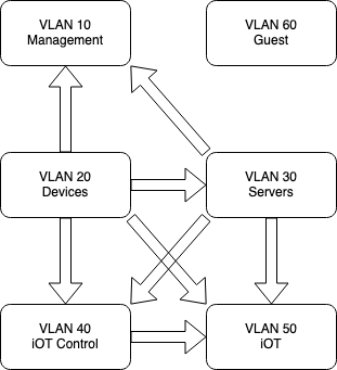
For example, there’s no reason a smart light bulb should ever need to talk to any other device on the network. Therefore I have a firewall rule for VLAN 50 that the only allowed traffic is to the internet. They can’t see or ping the local network at all.
Some iOT devices do need to see others on the network to function well, so those are on the iOT Control VLAN. This allows them to see each other, and all deviecs on the iOT network, but nothing else.
Servers can see all iOT devices, but nothing else.
All trusted devices can see everything and access everything.
And so on.
Next Steps
Once the physical and the virtual networks were setup, then came a huge bit of work to get the services setup to monitor, manage, and automate everything I wanted to. This will need to be another post.